-
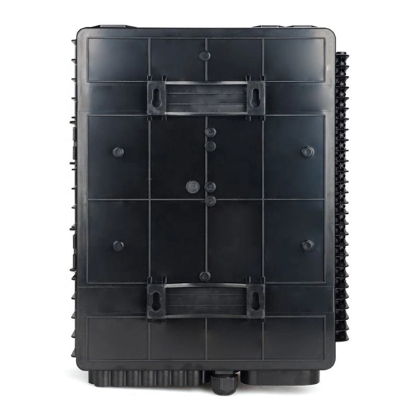
How much does a cold aisle server rack cost in China and Europe
The core reasons for choosing the Data Center Cold Aisle Cabinet are energy saving, stability, and peace of mind. In terms of cost, direct factory supply eliminates middlemen, resulting in procurement costs 20% lower than competitors. Get samples of US$ 5350/Piece ! US$ 5350/Piece Company Info. 4 mounting rails metal thickness 2. Supplier highlights: This supplier is both a manufacturer and trader, collaborating with Fortune 500 companies and excelling in quality control. These enclosures are designed to meet current IT market trends and applications ranging from high density computing and networking to broadcast and. The hot and cold aisle containment strategy is central to this modern data center optimization. The data center cooling market is experiencing significant expansion. -
-
-
-
-
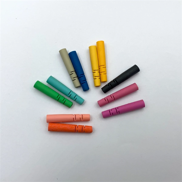
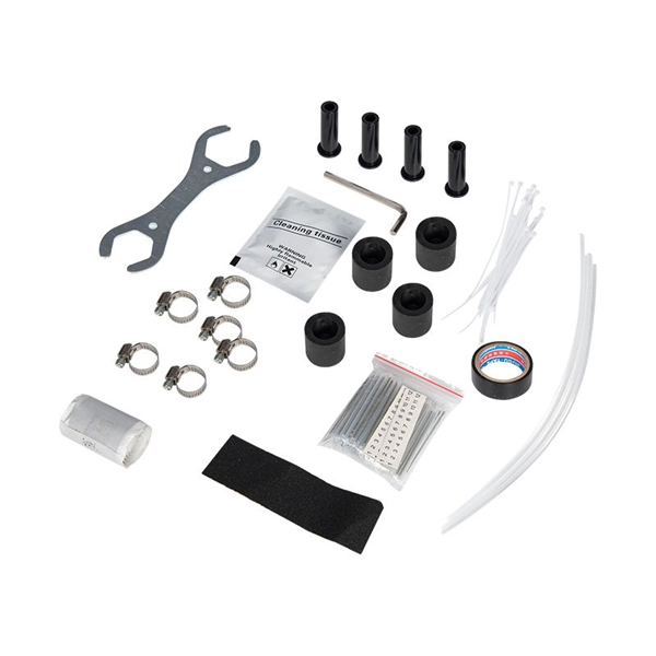
Custom-made protection for secondary distribution boxes
Our innovative secondary packaging solutions include our returnable solutions, our In The Box pre-assembled partition systems that are already integrated inside corrugated boxes, our Protectapack™ top void fill for the highest level of product protection, and our. Our innovative secondary packaging solutions include our returnable solutions, our In The Box pre-assembled partition systems that are already integrated inside corrugated boxes, our Protectapack™ top void fill for the highest level of product protection, and our. Group multiple primary packaged products or provide an additional layer of protection and branding with our protective and brand-reinforcing custom secondary boxes. These boxes are ideal for retail display, shipping bundles, and enhancing your overall brand presentation. Choose from our library of. Atexdelvalle offers world-class explosion-protected solutions guaranteeing highest quality and performance with no compromise. Manufacture custom made Local Control Stations & Distribution Boxes, local control panel boards and stations, explosion protected control units, distribution. Protective packaging is your key to successful fragile product shipment without damage and disappointed customers. It can act as the primary packing element or as a secondary piece, such as an insert that fits into a box, shielding your goods from harm caused by shock or vibration. Top and bottom flaps fully overlap, adding additional strength to protect your products from damage. Impress your customers with sturdy custom mailers. Made from durable materials like galvanized steel, they provide excellent corrosion resistance, mechanical strength, and long service life for both. -
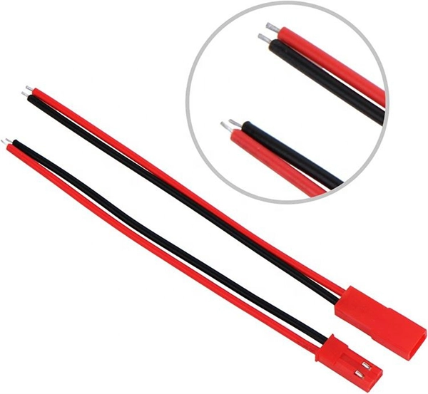
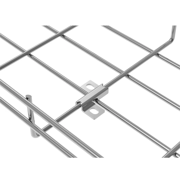
How much current flows in a 4-core self-supporting optical cable
The ADSS cable is suspended in the electrical field due to the phase conductors; this varies from a maximum at mid-span to zero at the grounded metal supports of the cable. In dry conditions, no current flows on the jacket of the cable, but moisture reduces the jacket. All-dielectric self-supporting (ADSS) cable is a type of optical fiber cable that is strong enough to support itself between structures without using conductive metal elements. mportant notices and legal disclaimers. MASS cable is a compact, light-weight solution. ADSS or All-Dielectric Self-Supporting Cables offer the best performance in high-voltage environments, long-distance installations, and extreme weather conditions. The tubes (and fillers) are stranded around the central strength member to form a cable core. The core is covered by water blocking tape and armored with steel tape. -
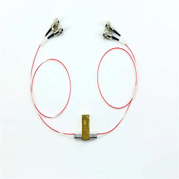
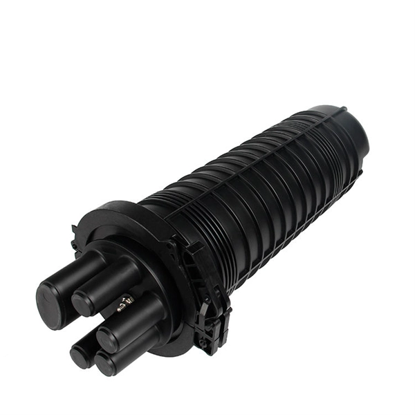
Hollow-core fiber optic connection
This paper describes a newly developed butt joint type hollow-core fiber connector with protected fiber ends. It can typically realize nearly 0.5-dB insertion and 45-dB return loss without physical contact. It has been confirmed that the HCF con. This paper describes a newly developed butt joint type hollow-core fiber connector with protected fiber ends. It can typically realize nearly 0.5-dB insertion and 45-dB return loss without physical contact. It has been confirmed that the HCF connector is suitable for actual use because it maintains stable connection characteristics in mating cycles, and it can be cleaned with an ordinary connector cleaner.••Studies of hollow-core fiber (HCF) have progressed,,,,,,, and recently a double nested antiresonant nodeless fiber (DNANF) with a propagation loss of 0.174 dB/km has been reported. This value indicates that DNANF has the potential to be used in optical communication networks. The single-mode fiber (SMF) that is currently used has an upper transmission capacity limit of 100 Tb/s due to the limitation of the power density of optical signals, but an HCF can expand the mode field diameter (MFD) propagated in a single mode without non-linearity effect nor fiber fuse phenomena. HCF is also attracting attention for its low-latency characteristic compared with silica fiber and its low dispersion, making it suitable for quantum communication. On the other hand, an optical connector is in. 2.1. Connection tolerances of butt-coupled HCFFor this study, we used IXF-ARF-45–240, Exail, which is a commercially available HCF with an anti-resonant structure. The fiber cross-section is shown in Fig. 1, and its characteristics are shown in Table 1.Fig. 1. Cross-sectional shape.Table 1. HCF characteristics.We investigated the relationship between misalignment and coupling loss when connecting this fiber with a butt joint. The measurement set up is shown in Fig. 2. An ASE (Amplified Spontaneous Emission) light source with a wavelength of 1460–1610 nm was used as the light source. The optical continuous wave reflectometer (OCWR) method was used to measure the return loss. An SMF and an HCF were coupled after numerica. We measured the connection characteristics of the HCF connectors. The measurement setup is shown in Fig. 10. As in Fig. 2, the HCF is excited from an SMF via the NA conversion module with a lens array. To eliminate higher-order modes, a 12-m long HCF with an HCF connector was used as a master plug, and the insertion and return loss of a 1-m long HCF patch cord connected to this master plug were measured. The insertion loss was measured from the ratio of the optical powers at points A and B shown in Fig. 10. The return loss was measured from the ratio of the optical power at point C when an Ag mirror was opposed to point A and the optical power at point C when a patch cord was connected to point A. The maximum return loss that can be measured with this measurement setup was 57 dB.Since it is not possible to polish the HCF endface and remove any dust adhering to it, we designed a prototype optical connector with a structure that protects the HCF endface with a thin glass plate. Although there is a large gap between the HCFs connected in this structure, it was expected that the excess loss could be kept low due to the small NA. The insertion loss of the prototype HCF connector is distributed in a range exceeding 0.3 dB as expected from the gap loss, and it is considered that the expected insertion loss was obtained. Since the dimensional accuracy of the stainless-steel ferrule is insufficient, we obtained a large excess loss. However, since there is room to improve the dimensional accuracy of the ferrule, we believe it is possible to achieve a lower insertion loss. -
Laser Diodes & VCSEL
High-power CW/pulsed laser diodes (808nm–1550nm) and VCSEL arrays for 3D sensing, LIDAR, and optical interconnects.
Silicon Photonics & CPO
Co-packaged optics engines, silicon photonics ICs, and optical I/O solutions for high-density switches and AI clusters.
Optical Transceivers & AOCs
400G/800G QSFP-DD/OSFP modules, active optical cables, and custom optical engines for data center interconnects.
Laser Drivers & CDR
Low-jitter laser drivers, integrated CDR circuits, and linear TIAs for coherent optics and short-reach links.